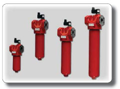
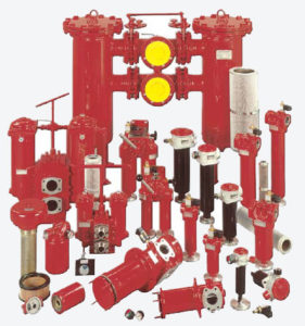
LF-RF series
Application: For installation in a suction, discharge or discharge line.
Connection: threaded to G ѕ, flanged to DIN / ANSI 10 ”
Working pressure: 10, 16, 25 or 32 bar
Consumption: up to 10000 l / min
Filtration material: paper fiber, fiberglass, stainless steel mesh.
Design features: The filter is installed in the pipeline, the inlet and outlet openings are on the same axis. Can function as a suction, pressure or drain filter. The RF filter has a side inlet and an outlet in the lower part.
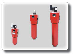
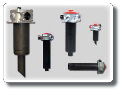
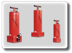
ML Series – MNL
 Application: For installation in a pressure line – with threaded connection.
Connection: Screwed to G 1
Working pressure: up to 160 bar
Consumption: up to 450 l / min
Filtration material: fiberglass, stainless steel mesh
Design features: compact filter for small and medium pressure. A minimum space is required to change the filter element.
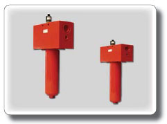
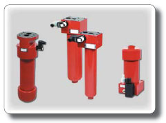
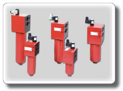
HP 31-451 Series
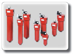 Application: For installation in a pressure line – with threaded connection.
Connection: threaded up to G 1.5
Working pressure: up to 420 bar
Consumption: up to 450 l / min
Filtration material: paper fiber, fiberglass, stainless steel mesh
Design features: Pressure filter for installation in pipelines.
HP 170-1350 Series
 Application: For installation in a pressure line – with flange connection.
Connection: flanged to SAE 1.5 ”
Working pressure: up to 420 bar
Consumption: up to 1350 l / min
Filtration material: paper fiber, fiberglass, stainless steel mesh
Design features: Pressure filter for installation in pipelines. The maximum flow is possible.
HPW Series
 Application: Pressure filter with replaceable flow direction
Connection: threaded up to G 1.5 flanged to DN 50
Working pressure: up to 315 bar
Consumption: up to 400 l / min
Filtration material: paper fiber, fiberglass, stainless steel mesh
Design features: The pressure filter of this series is designed for the case of exchangeable flow directions. Filtering is performed in both cases.
HPV-MDV Series
 Application: Pressure filter with cold start valve
Connection: HPV – threaded to G 1.5, MDV – threaded to G 3/4
Working pressure: HPV – up to 420 bar, MDV – up to 200 bar
Consumption: HPV – up to 450 l / min, MDV – up to 150 l / min
Filtration material: paper fiber, fiberglass, stainless steel mesh
Structural features: Stable filtration is ensured. To avoid equipment failure, the contaminated filter element must be replaced immediately. Forced discharge of liquid into the intermediate tank by means of the third connection.


 Application: Tank mounted return-line filters with suction connection for mobile hydraulic applications with minimum two independent hydraulic circuits.
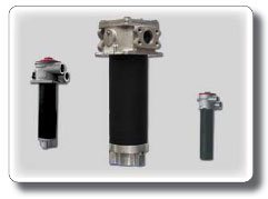 Application: Can be mounted in suction, pressure or return lines.
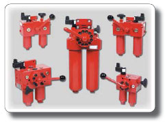 произвести во всасывающей, напорной или сливной линии.
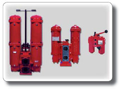 произвести во всасывающей, напорной или сливной линии.
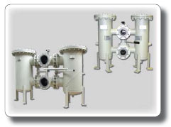 произвести во всасывающей, напорной или сливной линии.
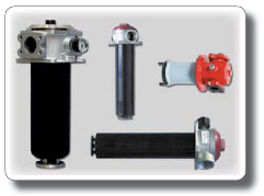
 Application: The filter of the parallel filtration is designed for the side contour – in addition to the main one.
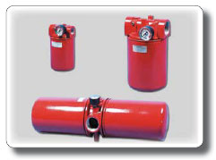 Application: filter for installation in suction and drain lines
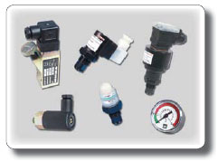 Application: A wide range of pollution degree indicators for hydraulic systems and lubrication systems
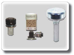 Application: The breathing apparatus prevents the penetration of dust and moisture into hydraulic tanks
 Application: Pressure filter with flange connection to mounting surface
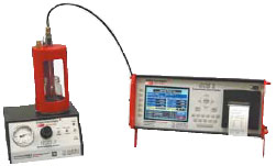
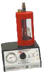
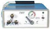
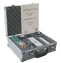
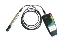
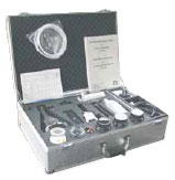 PAS01 – kit for taking and analyzing oil samples
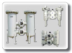
 UM / US-m mobile and fixed installations of parallel filtration
 USP- Parallel filter units with integrated heat exchanger
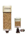
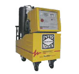 IFPM / IFPS-C System for removing water from hydraulic fluids